- 您现在的位置:买卖IC网 > Sheet目录279 > 101-0523 (Rabbit Semiconductor)KIT DEV RABBIT3000/RCM3000
�� �
�
�2.2� Hardware� Connections�
�2.2.1� Attach� Module� to� Prototyping� Board�
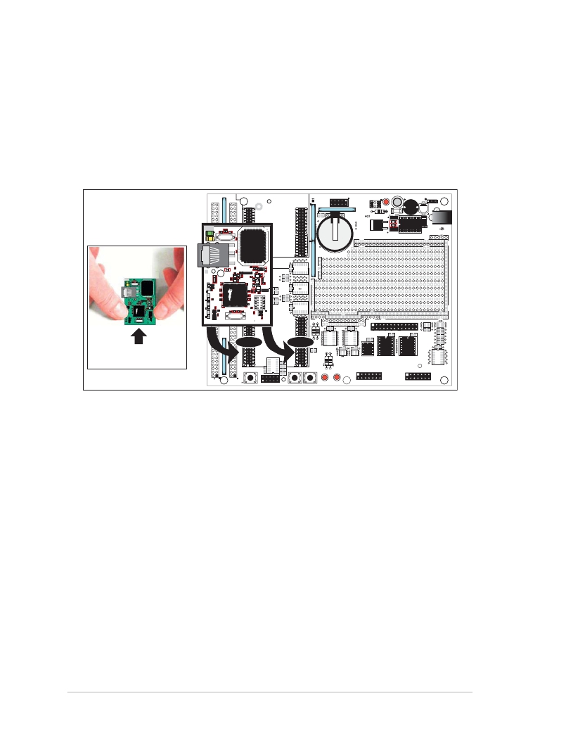
�Turn� the� RCM3000� module� so� that� the� Ethernet� connector� end� of� the� module� extends� off�
�the� Prototyping� Board,� as� shown� in� Figure� 1� below.� Align� the� pins� from� headers� J1� and� J2�
�on� the� bottom� side� of� the� module� into� header� sockets� RCM2JA� and� RCM2JB� on� the� Proto-�
�typing� Board� (these� sockets� were� labeled� J12� and� J13� on� earlier� versions� of� the� Prototyping�
�Board).�
�RN1�
�L1�
�GND�
�GND�
�VBAT�
�EXT�
�/RES�
�IN�
�SM0�
�NC�
�+3.3V�
�VRAM�
�SM1�
�/IORD�
�PD1�
�PD7�
�PD3�
�PD5�
�PG3�
�PD0�
�PD6�
�PD2�
�PD4�
�PG2�
�RCM1JA�
�GND�
�RCM3000� ETHERNET� CORE� MODULE�
�RCM1JB�
�RN5�
�R17�
�R20�
�C13�
�D1�
�C17�
�J11�
�/IOWR�
�PG4�
�PG1�
�PG0�
�RCM3000�
�PG5�
�PG7�
�PE1�
�PG6�
�PE0�
�PE3�
�PD4�
�PC5�
�PC3�
�PD5�
�PC4�
�PC2�
�U4�
�C12�
�U5�
�D2�
�2.5� MM� JACK�
�GND� +DC�
�PE4�
�PE6�
�PF7�
�PF5�
�PE5�
�PE7�
�PF6�
�PF4�
�PC1�
�PF0�
�PF2�
�PA0�
�PC0�
�PF1�
�PF3�
�PA1�
�Battery�
�+5V�
�+3.3V�
�+5V�
�+3.3V�
�PB7�
�PB6�
�PA2�
�PA3�
�PB5�
�PB4�
�PA4�
�PA5�
�BT1�
�PB3�
�PB0�
�J1�
�PB2�
�/RES�
�R1�
�PA6�
�PE4�
�J3�
�C1�
�PA7�
�GND�
�R4�
�RC15�
�RC19�
�RC20�
�UX10�
�SLAVE�
�MASTER�
�RCM2�
�RC23�
�RC24�
�UX11�
�J15�
�R3�
�R2�
�C3�
�R5�
�RC13�
�RC14�
�RC17�
�RC16�
�UX9�
�RC22�
�R21�
�RC12�
�RC10�
�RC11�
�UX3�
�RC21�
�RC2�
�UX2�
�GND�
�GND�
�GND�
�GND�
�RCM2JA�
�DISPLAY� BOARD�
�Donotpressdown�
�here.�
�GND�
�GND�
�VBAT�
�EXT�
�/RES�
�IN�
�SM0�
�/IOWR�
�PG5�
�PG7�
�PE1�
�PE4�
�PE6�
�PF7�
�PF5�
�PB7�
�PB5�
�PB3�
�PB0�
�NC� PD1�
�+3.3V� PD7�
�VRAM� PD3�
�SM1� PD5�
�/IORD� PG3�
�PG4� PG1�
�PG6� PD4�
�PE0� PC5�
�PE3� PC3�
�PE5� PC1�
�PE7� PF0�
�PF6� PF2�
�PF4� PA0�
�PB6� PA2�
�PB4� PA4�
�PB2� PA6�
�/RES� STATUS�
�J4�
�PD0�
�PD6�
�PD2�
�PD4�
�PG2�
�PG0�
�PD5�
�PC4�
�PC2�
�PC0�
�PF1�
�PF3�
�PA1�
�PA3�
�PA7�
�GND�
�PA5� RCM2JA�
�RESET�
�RxC� TxC�
�U1�
�J5�
�C7�
�C5�
�C8�
�C6�
�RCM2JB�
�R14�
�RCM2JB�
�S2� S3�
�+3.3V�
�+3.3V�
�+5V�
�PG6�
�UX5�
�RC6�
�PG7�
�RC9�
�RC7�
�UX7�
�+3.3V�
�+5V�
�U3�
�+3.3V� +5V�
�J8�
�C16�
�U6�
�C9�
�RCM30/31/32XX� SERIES�
�PROTOTYPING� BOARD�
�J10� J7�
�C14�
�U3�
�UX4�
�RC4�
�RC26�
�+5V�
�UX13�
�RC25�
�RC5�
�RC27�
�RC28�
�RC29�
�TxB� RxB�
�GND�
�RS-232�
�DS1�
�DS2�
�DISPLAY� BOARD�
�DISPLAY� BOARD�
�Figure� 1.� Install� the� RCM3000� Module� on� the� Prototyping� Board�
�Although� you� can� install� a� single� module� into� either� the� MASTER� or� the� SLAVE� position�
�on� the� Prototyping� Board,� all� the� Prototyping� Board� features� (switches,� LEDs,� serial� port�
�drivers,� etc.)� are� connected� to� the� MASTER� position� —� install� a� single� module� in� the�
�MASTER� position.�
�NOTE:� It� is� important� that� you� line� up� the� pins� on� headers� J1� and� J2� of� the� RCM3000�
�module� exactly� with� the� corresponding� pins� of� sockets� RCM2JA� and� RCM2JB� on� the�
�Prototyping� Board.� The� header� pins� may� become� bent� or� damaged� if� the� pin� alignment�
�is� offset,� and� the� module� will� not� work.� Permanent� electrical� damage� to� the� module� may�
�also� result� if� a� misaligned� module� is� powered� up.�
�Press� the� module’s� pins� firmly� into� the� Prototyping� Board� header� sockets—press� down� in�
�the� area� above� the� header� pins� using� your� thumbs� or� fingers� over� the� connectors� as� shown�
�in� Figure� 1.� Do� not� press� down� on� the� middle� of� the� RCM3000� module� to� avoid� flexing�
�the� module,� which� could� damage� the� module� or� the� components� on� the� module.�
�Should� you� need� to� remove� the� RCM3000� module,� grasp� it� with� your� fingers� along� the� sides�
�by� the� connectors� and� gently� work� the� module� up� to� pull� the� pins� away� from� the� sockets�
�where� they� are� installed.� Do� not� remove� the� module� by� grasping� it� at� the� top� and� bottom.�
�6�
�RabbitCore� RCM3000�
�发布紧急采购,3分钟左右您将得到回复。
相关PDF资料
101-1109
KIT EMBEDDED PLC APPLICATION
101-1147
KIT RIO PROGRAM I/O
101-606
CONN SOCKET IDC 60POS W/KEY GOLD
10113616-01531LF
CONN MOD JACK 8PORT 8/8 R/A PCB
10117863-5036010LF
CONN MOD JACK 8/8 R/A PCB
10118061-5005010LF
CONN MOD JACK 2PORT 8/8 R/A PCB
10118062-5001310LF
CONN MOD JACK 4PORT 8/8 R/A PCB
10118063-5001310LF
CONN MOD JACK 6PORT 8/8 R/A PCB
相关代理商/技术参数
101-0524
功能描述:KIT DEV RABBIT RCM3000 INTL RoHS:否 类别:编程器,开发系统 >> 通用嵌入式开发板和套件(MCU、DSP、FPGA、CPLD等) 系列:RabbitCore 3000 产品培训模块:Blackfin® Processor Core Architecture Overview
Blackfin® Device Drivers
Blackfin® Optimizations for Performance and Power Consumption
Blackfin® System Services 特色产品:Blackfin? BF50x Series Processors 标准包装:1 系列:Blackfin® 类型:DSP 适用于相关产品:ADSP-BF548 所含物品:板,软件,4x4 键盘,光学拨轮,QVGA 触摸屏 LCD 和 40G 硬盘 配用:ADZS-BFBLUET-EZEXT-ND - EZ-EXTENDER DAUGHTERBOARDADZS-BFLLCD-EZEXT-ND - BOARD EXT LANDSCAP LCD INTERFACE 相关产品:ADSP-BF542BBCZ-4A-ND - IC DSP 16BIT 400MHZ 400CSBGAADSP-BF544MBBCZ-5M-ND - IC DSP 16BIT 533MHZ MDDR 400CBGAADSP-BF542MBBCZ-5M-ND - IC DSP 16BIT 533MHZ MDDR 400CBGAADSP-BF542KBCZ-6A-ND - IC DSP 16BIT 600MHZ 400CSBGAADSP-BF547MBBCZ-5M-ND - IC DSP 16BIT 533MHZ MDDR 400CBGAADSP-BF548BBCZ-5A-ND - IC DSP 16BIT 533MHZ 400CSBGAADSP-BF547BBCZ-5A-ND - IC DSP 16BIT 533MHZ 400CSBGAADSP-BF544BBCZ-5A-ND - IC DSP 16BIT 533MHZ 400CSBGAADSP-BF542BBCZ-5A-ND - IC DSP 16BIT 533MHZ 400CSBGA
101-0525
功能描述:开发板和工具包 - 其他处理器 LP3500 RoHS:否 制造商:Freescale Semiconductor 产品:Development Systems 工具用于评估:P3041 核心:e500mc 接口类型:I2C, SPI, USB 工作电源电压:
101-0526
功能描述:开发板和工具包 - 其他处理器 LP3510 RoHS:否 制造商:Freescale Semiconductor 产品:Development Systems 工具用于评估:P3041 核心:e500mc 接口类型:I2C, SPI, USB 工作电源电压:
101-0529
功能描述:开发板和工具包 - 其他处理器 LP3500 Tool Kit
RoHS:否 制造商:Freescale Semiconductor 产品:Development Systems 工具用于评估:P3041 核心:e500mc 接口类型:I2C, SPI, USB 工作电源电压:
101053
制造商:RUKO 功能描述:Bulk
101-0530
功能描述:开发板和工具包 - 其他处理器 LP3500 TOOLKIT Univr
RoHS:否 制造商:Freescale Semiconductor 产品:Development Systems 工具用于评估:P3041 核心:e500mc 接口类型:I2C, SPI, USB 工作电源电压:
101-0531
功能描述:单板计算机 BL2101 0-10V A/D RoHS:否 制造商:Ampro By ADLINK 外观尺寸:EPIC 处理器类型:Intel Atom D510 频率:1.66 GHz 存储容量:2 GB (max) 存储类型:DDR2, L2 Cache 接口类型:Ethernet, PS/2, SATA, Serial, USB 工作电源电压:5 V, 12 V 功耗:13 W 最大工作温度:+ 70 C 尺寸:165.1 mm x 114.3 mm
10-105310-02P
制造商:Amphenol Aerospace 功能描述:RECEPT