- 您现在的位置:买卖IC网 > Sheet目录279 > 101-0523 (Rabbit Semiconductor)KIT DEV RABBIT3000/RCM3000
2.2 Hardware Connections
2.2.1 Attach Module to Prototyping Board
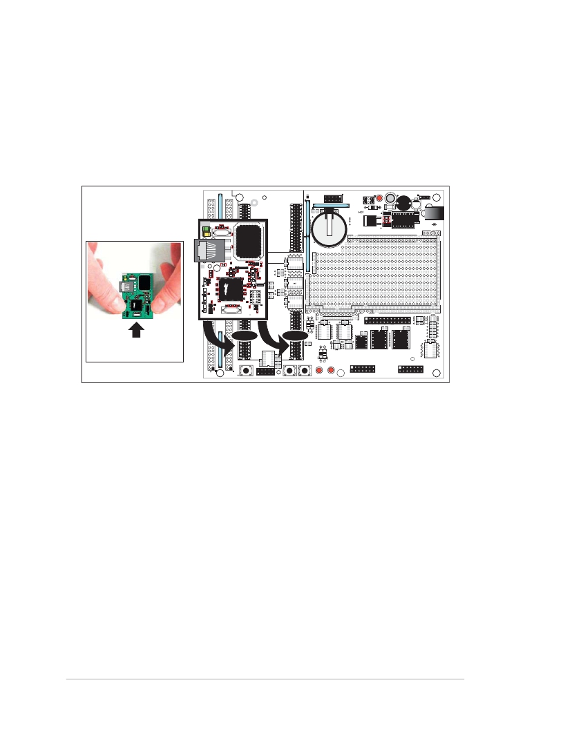
Turn the RCM3000 module so that the Ethernet connector end of the module extends off
the Prototyping Board, as shown in Figure 1 below. Align the pins from headers J1 and J2
on the bottom side of the module into header sockets RCM2JA and RCM2JB on the Proto-
typing Board (these sockets were labeled J12 and J13 on earlier versions of the Prototyping
Board).
RN1
L1
GND
GND
VBAT
EXT
/RES
IN
SM0
NC
+3.3V
VRAM
SM1
/IORD
PD1
PD7
PD3
PD5
PG3
PD0
PD6
PD2
PD4
PG2
RCM1JA
GND
RCM3000 ETHERNET CORE MODULE
RCM1JB
RN5
R17
R20
C13
D1
C17
J11
/IOWR
PG4
PG1
PG0
RCM3000
PG5
PG7
PE1
PG6
PE0
PE3
PD4
PC5
PC3
PD5
PC4
PC2
U4
C12
U5
D2
2.5 MM JACK
GND +DC
PE4
PE6
PF7
PF5
PE5
PE7
PF6
PF4
PC1
PF0
PF2
PA0
PC0
PF1
PF3
PA1
Battery
+5V
+3.3V
+5V
+3.3V
PB7
PB6
PA2
PA3
PB5
PB4
PA4
PA5
BT1
PB3
PB0
J1
PB2
/RES
R1
PA6
PE4
J3
C1
PA7
GND
R4
RC15
RC19
RC20
UX10
SLAVE
MASTER
RCM2
RC23
RC24
UX11
J15
R3
R2
C3
R5
RC13
RC14
RC17
RC16
UX9
RC22
R21
RC12
RC10
RC11
UX3
RC21
RC2
UX2
GND
GND
GND
GND
RCM2JA
DISPLAY BOARD
Donotpressdown
here.
GND
GND
VBAT
EXT
/RES
IN
SM0
/IOWR
PG5
PG7
PE1
PE4
PE6
PF7
PF5
PB7
PB5
PB3
PB0
NC PD1
+3.3V PD7
VRAM PD3
SM1 PD5
/IORD PG3
PG4 PG1
PG6 PD4
PE0 PC5
PE3 PC3
PE5 PC1
PE7 PF0
PF6 PF2
PF4 PA0
PB6 PA2
PB4 PA4
PB2 PA6
/RES STATUS
J4
PD0
PD6
PD2
PD4
PG2
PG0
PD5
PC4
PC2
PC0
PF1
PF3
PA1
PA3
PA7
GND
PA5 RCM2JA
RESET
RxC TxC
U1
J5
C7
C5
C8
C6
RCM2JB
R14
RCM2JB
S2 S3
+3.3V
+3.3V
+5V
PG6
UX5
RC6
PG7
RC9
RC7
UX7
+3.3V
+5V
U3
+3.3V +5V
J8
C16
U6
C9
RCM30/31/32XX SERIES
PROTOTYPING BOARD
J10 J7
C14
U3
UX4
RC4
RC26
+5V
UX13
RC25
RC5
RC27
RC28
RC29
TxB RxB
GND
RS-232
DS1
DS2
DISPLAY BOARD
DISPLAY BOARD
Figure 1. Install the RCM3000 Module on the Prototyping Board
Although you can install a single module into either the MASTER or the SLAVE position
on the Prototyping Board, all the Prototyping Board features (switches, LEDs, serial port
drivers, etc.) are connected to the MASTER position — install a single module in the
MASTER position.
NOTE: It is important that you line up the pins on headers J1 and J2 of the RCM3000
module exactly with the corresponding pins of sockets RCM2JA and RCM2JB on the
Prototyping Board. The header pins may become bent or damaged if the pin alignment
is offset, and the module will not work. Permanent electrical damage to the module may
also result if a misaligned module is powered up.
Press the module’s pins firmly into the Prototyping Board header sockets—press down in
the area above the header pins using your thumbs or fingers over the connectors as shown
in Figure 1. Do not press down on the middle of the RCM3000 module to avoid flexing
the module, which could damage the module or the components on the module.
Should you need to remove the RCM3000 module, grasp it with your fingers along the sides
by the connectors and gently work the module up to pull the pins away from the sockets
where they are installed. Do not remove the module by grasping it at the top and bottom.
6
RabbitCore RCM3000
发布紧急采购,3分钟左右您将得到回复。
相关PDF资料
101-1109
KIT EMBEDDED PLC APPLICATION
101-1147
KIT RIO PROGRAM I/O
101-606
CONN SOCKET IDC 60POS W/KEY GOLD
10113616-01531LF
CONN MOD JACK 8PORT 8/8 R/A PCB
10117863-5036010LF
CONN MOD JACK 8/8 R/A PCB
10118061-5005010LF
CONN MOD JACK 2PORT 8/8 R/A PCB
10118062-5001310LF
CONN MOD JACK 4PORT 8/8 R/A PCB
10118063-5001310LF
CONN MOD JACK 6PORT 8/8 R/A PCB
相关代理商/技术参数
101-0524
功能描述:KIT DEV RABBIT RCM3000 INTL RoHS:否 类别:编程器,开发系统 >> 通用嵌入式开发板和套件(MCU、DSP、FPGA、CPLD等) 系列:RabbitCore 3000 产品培训模块:Blackfin® Processor Core Architecture Overview
Blackfin® Device Drivers
Blackfin® Optimizations for Performance and Power Consumption
Blackfin® System Services 特色产品:Blackfin? BF50x Series Processors 标准包装:1 系列:Blackfin® 类型:DSP 适用于相关产品:ADSP-BF548 所含物品:板,软件,4x4 键盘,光学拨轮,QVGA 触摸屏 LCD 和 40G 硬盘 配用:ADZS-BFBLUET-EZEXT-ND - EZ-EXTENDER DAUGHTERBOARDADZS-BFLLCD-EZEXT-ND - BOARD EXT LANDSCAP LCD INTERFACE 相关产品:ADSP-BF542BBCZ-4A-ND - IC DSP 16BIT 400MHZ 400CSBGAADSP-BF544MBBCZ-5M-ND - IC DSP 16BIT 533MHZ MDDR 400CBGAADSP-BF542MBBCZ-5M-ND - IC DSP 16BIT 533MHZ MDDR 400CBGAADSP-BF542KBCZ-6A-ND - IC DSP 16BIT 600MHZ 400CSBGAADSP-BF547MBBCZ-5M-ND - IC DSP 16BIT 533MHZ MDDR 400CBGAADSP-BF548BBCZ-5A-ND - IC DSP 16BIT 533MHZ 400CSBGAADSP-BF547BBCZ-5A-ND - IC DSP 16BIT 533MHZ 400CSBGAADSP-BF544BBCZ-5A-ND - IC DSP 16BIT 533MHZ 400CSBGAADSP-BF542BBCZ-5A-ND - IC DSP 16BIT 533MHZ 400CSBGA
101-0525
功能描述:开发板和工具包 - 其他处理器 LP3500 RoHS:否 制造商:Freescale Semiconductor 产品:Development Systems 工具用于评估:P3041 核心:e500mc 接口类型:I2C, SPI, USB 工作电源电压:
101-0526
功能描述:开发板和工具包 - 其他处理器 LP3510 RoHS:否 制造商:Freescale Semiconductor 产品:Development Systems 工具用于评估:P3041 核心:e500mc 接口类型:I2C, SPI, USB 工作电源电压:
101-0529
功能描述:开发板和工具包 - 其他处理器 LP3500 Tool Kit
RoHS:否 制造商:Freescale Semiconductor 产品:Development Systems 工具用于评估:P3041 核心:e500mc 接口类型:I2C, SPI, USB 工作电源电压:
101053
制造商:RUKO 功能描述:Bulk
101-0530
功能描述:开发板和工具包 - 其他处理器 LP3500 TOOLKIT Univr
RoHS:否 制造商:Freescale Semiconductor 产品:Development Systems 工具用于评估:P3041 核心:e500mc 接口类型:I2C, SPI, USB 工作电源电压:
101-0531
功能描述:单板计算机 BL2101 0-10V A/D RoHS:否 制造商:Ampro By ADLINK 外观尺寸:EPIC 处理器类型:Intel Atom D510 频率:1.66 GHz 存储容量:2 GB (max) 存储类型:DDR2, L2 Cache 接口类型:Ethernet, PS/2, SATA, Serial, USB 工作电源电压:5 V, 12 V 功耗:13 W 最大工作温度:+ 70 C 尺寸:165.1 mm x 114.3 mm
10-105310-02P
制造商:Amphenol Aerospace 功能描述:RECEPT
